 ENEN
ENEN
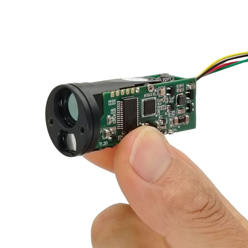
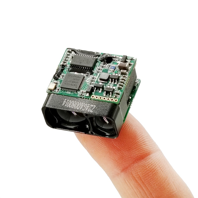
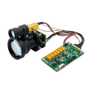
Product performance index:
| Project Name | STA-LR1500D |
| Human eye safety | Yes |
| Laser wavelength | 905nm |
| Laser divergence angle | 1×6mrad |
| Receiving field of view | ~20mrad |
| Transmitter Caliber | Φ10×7.5mm |
| Receiving caliber | Φ15×10mm |
| Ranging range | 5~1200m |
| Ranging accuracy | ±1m |
| Measuring frequency | Single-shot ranging,1Hz,2Hz |
| Accuracy rate | ≥98% |
| False alarm rate | ≤1% |
| Data Interface | UART(TTL_3.3V) |
| Supply voltage | DC 3~5 V |
| Power consumption | Standby: ≤0.6W@3.3V; |
| Work: ≤1W@3.3V; | |
| Weights | 10±0.5g |
| Size(L×W×H) | ≤26×25×13.5mm |
| Operating temperature | -20~+60℃ |
| Storage temperature | -30~+60℃ |
| Shock | 1200g,1ms |
| Vibration | 5~50~5Hz, 1 octave/min, 2.5g |
| Reliability | MTBF≥1500h |
| Start-up time | ≤200ms; |
| Electrical interface | Socket: 0.8WTB-6AB-01
Plug: 0.8WTB-6Y-2 |
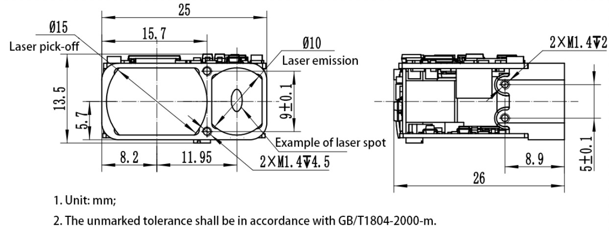
Structure installation interface:
The external dimensions of the mechanical and optical interfaces are shown in Figure 2.
Electrical interface:
The electrical interface requirements are as follows:
a) Power supply voltage: 3V~5.5V (typical value 3.3V or 5V);
b) Standby power consumption: ≤ 0.8W;
c) Average power consumption: ≤ 1W;
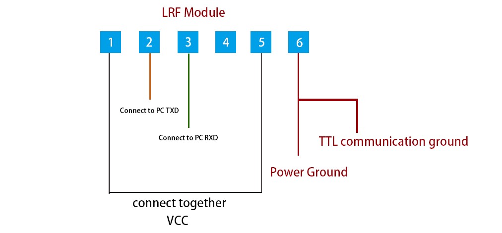
d) The upper computer end achieves cross-linking testing with the distance measuring machine end 0.8WTB-6AB-01 connector (Yueqing Huabao) through the 0.8WTB-6Y-2 connector. The definitions of the power supply and communication port pins on the rangefinder end are shown in Table 1, and the connector pin positions are shown in Figure 3.
Table 2 Definition of Product Electrical Pin
| Pin | Labeling | Electrical Characteristics Definition | Signal direction |
| 1 | Power-EN | ||
| 2 | TTL_RXD | Signal input port | Host computer to rangefinder |
| 3 | TTL_TXD | Signal output port | Rangefinder to host computer |
| 4 | NC | ||
| 5 | Power supply+ | ||
| 6 | GND |
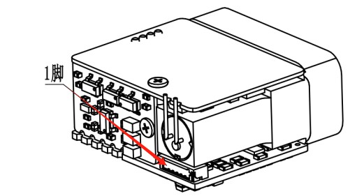
Figure 3: 1 Pin
Electrical Connection Diagram